Installation Guidelines for Fabricated Access Covers
PRE- DELIVERY CHECKS
Before dispatch, all covers and frames manufactured by FSP are fully assembled (locked, sealed and marked with identification numbers where applicable) and rigorously checked for dimensional accuracy, quality and overall fitness for purpose in accordance with ISO: 9001 quality system.
INSTALLATION SEQUENCE
Dimensional checks must be carried out on frame before setting into position. This is especially important on frames over 1m in length and width. Following checks must be done;
STEP 1 –
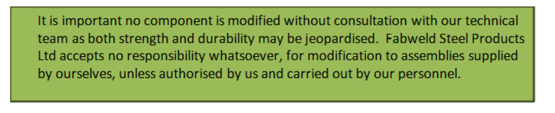
Centralise cover and frame over chamber, making sure frame is fully supported and the clear opening of the frame aligns with the chamber/manhole opening. Loosely position frame and mark for drilling of 10mm hole to suit M12 Hexagon Head Anchor Fixings (COM0000309)
Clear opening marked with blue arrows.
STEP 2 –
Set frame to required level with mineral or metallic packing, and adjust as necessary ensuring frame fixing bolts are not fully tightened. Check to ensure cover is aligned with finished floor level, adjust packing material as necessary.
STEP 3 –
To ensure integrity, any unsupported areas of the frame must be filled with a suitable grouting material and be allowed to fully harden. When grouting is fully cured, check that covers can be removed from frame freely, before final screeding or concreting takes place.
ADDITONAL NOTES
When screeding or concreting to finished floor level care must be taken to ensure debris does not enter the locking down boltholes and lifting key slots or seals. It is particularly important to ensure that if concrete or screed enters the keyway it gets removed before curing commences. Always refer to concrete suppliers’ guidelines for cure times before covers are trafficked.
MULTI-PART COVERS
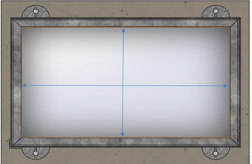
- Handling & lifting – all lifting points (red arrows) must be used to ensure a safe-lift.
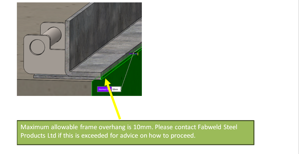
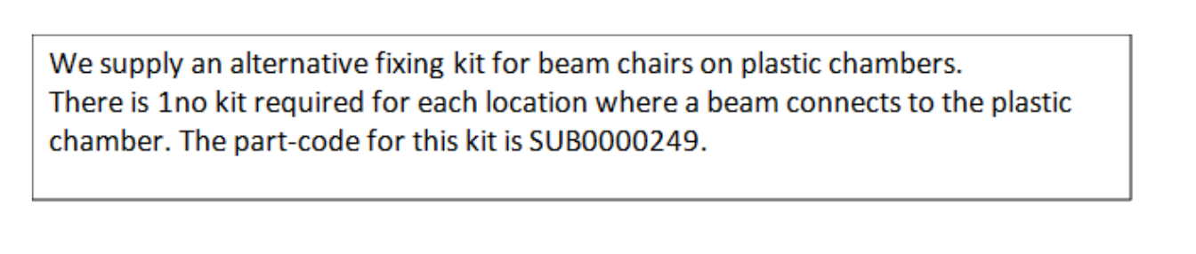
- Beam support plates should always be secured in the vertical position with suitable anchor bolts – see ‘Anchors’ section.
- Frames on multi-part units need to be lifted using the sling points, these are shown in red. Split-frames should only be lifted as separate units, the fixing bolts are only designed to hold the frame in position prior to grouting.
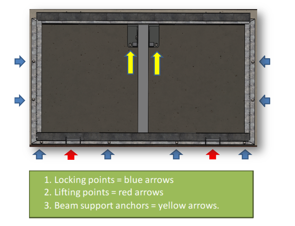
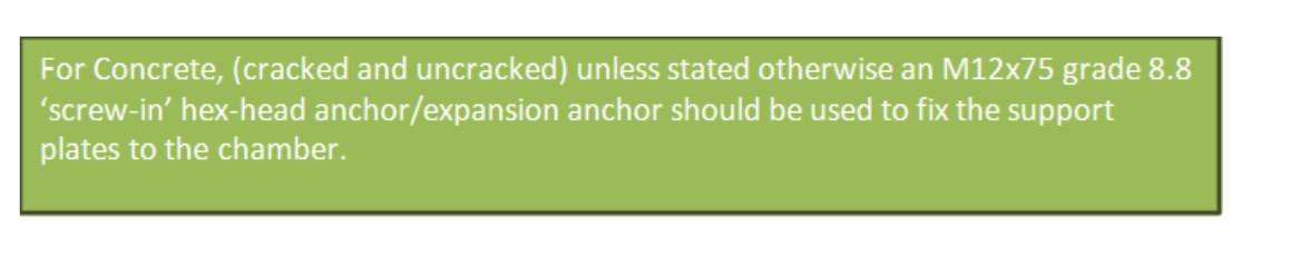
SUPPORT PLATES


CONTINUOUS DUCTING
- Centralise frame over duct; removing and replacing covers one at a time in sequential order as per identification markings on the covers and frames or the drawings provided to ensure correct alignment.
- If locking down bolts are specified, insert into the appropriate location but do not fully tighten to allow movement of the cover and ensure any removable support mechanisms are in place.
- Set frame to required level with mineral or metallic packing, and adjust as necessary ensuring frame fixing bolts are not fully tightened.
- Check to ensure cover is aligned with finished floor level, adjust packing material as necessary.
- To ensure integrity, any unsupported areas of the frame must be back filled with a suitable grouting material and be allowed to fully harden.
- When grouting is fully cured, check that covers can be removed from frame freely, before final screeding or concreting takes place. All recessed covers should be filled in their frames, unless supplied pre-filled
- When screeding or concreting to finished floor level, care must be taken to ensure debris does not enter the locking down boltholes and lifting key slots or seals. It is particularly important to ensure that if concrete or screed enters the keyway it gets removed before curing commences.
- It is imperative that all frame joints are set at the same vertical and horizontal alignment and that when covers are in situ, frame and cover surfaces are flush.
- To ensure perfect alignment, it is advisable that during duct assembly where it may occupy a visually prominent position, spacers are inserted between covers and their frames during screeding.
- When covers are supplied with support mechanisms that are not an integral part of the frame, it is advised that the supplied support pockets are fixed to the chamber wall using the preferred fixing method detailed in ‘Anchors’ below.
SEALING
Neoprene seals should be cleaned to remove debris, to guarantee seal integrity is not compromised. Once the screed has fully cured, and before traffic is admitted to the area, covers should be removed and sealing areas cleared. All covers locked onto a neoprene gasket provide an airtight seal when the cover and frame have been installed correctly.
We do not guarantee a cover to be fluid or gas tight unless specifically designed to do so.
RECESSED COVERS
- Recessed covers rely on the concrete infill to achieve the rated load bearing performance, this is based on filling with a minimum grade of C50 concrete. Covers should not be trafficked for 28 days from pouring the concrete, or whenever 50 MPa is achieved by means of test.
- It is important to fill the cover in its frame without distortion (ensure the cover is flat prior to filling). No locking screws should be removed before infilling. Care must be taken to protect the locking screws lifting key slots etc. from being blocked by concrete or resin mortar.
- Recessed covers for ‘solid’ infill such as block paviors or slabs will normally be 20-30mm deeper in the recess to enable the infill to sit on a bed of sand. If the covers have a key mesh on the base this means the infill should be bedded on an epoxy mortar.
Anchors
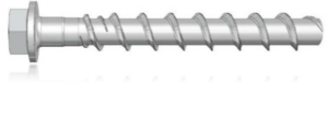
Screw-in anchor
Expansion anchor
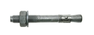
Whether a ‘screw-in’ or expansion type anchors is used will depend on the chamber material and conditions.
- Screw in anchors generate the resistance along the full-length of the anchor.
- Expansion anchors generate the resistance along the more concentrated bulbus section of the anchor.
These characteristics, along with the chamber material, will determine which anchor needs to be used.
RECOMMENDED ANCHORS FOR PLASTIC CHAMBERS
Suitable mesh-sleeve anchor which enables a column of mortar to fill the gap.
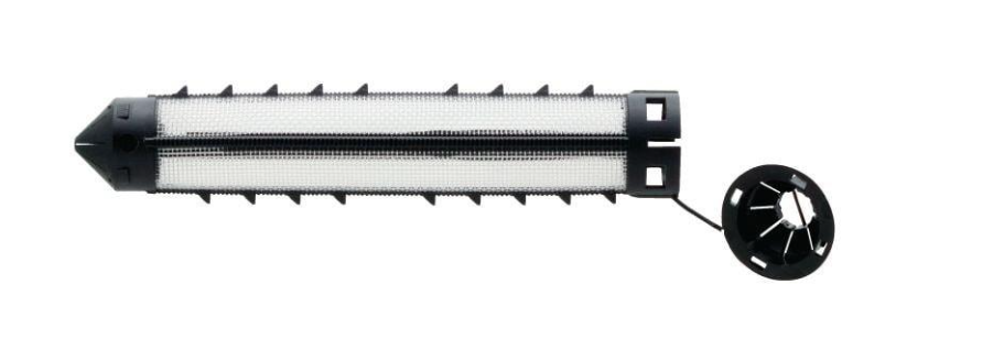
Notes
- Drill a 12mm hole through both walls of the chamber
- Insert Mesh sleeve so it slightly protrudes each end – sleeves can be clipped together to form a larger sleeve if necessary.
- Using a suitable mortar such as HIT-HY 270 Adhesive to fill the sleeve. Using a suitable mortar such as HIT-HY 270 Adhesive to fill the sleeve.
- Insert M12 grade 8.8 threaded anchor road, such as Hilti anchor rod
- Leave to set as per mortar instructions and tighten with M12 nut.
General Maintenance
All access covers supplied by Fabweld steel products must be lifted using all lifting points available, unless noted otherwise. Using another manufacturers lifting key may damage the lifting point. Whenever covers are removed from the frames the seating area should be cleaned with a soft brush before re inserting covers (failure to do this can cause rocking and affect performance). Wherever locking screws are removed grease should be re applied to the locking screws before reinstating the covers. Always ensure the locking points are free from debris before re-inserting the locking screws.

Important Notes
All of our products go through a rigorous quality check. If the cover is rocking in the frame, please check that that there is nothing clashing on the underside of the cover and the chamber. Finally, double check by removing the cover from the frame and placing on a flat surface.
If you have a product supplied with gas rams, please refer to alterative installation guidelines, which will accompany your product. Hinged covers with accessories (safety stays, turnbuckle locks, torsion spring assistance, etc) will be fixed and assembled at FSP to ensure perfect alignment. At no time must any component be removed or tampered with. The performance of fabricated access covers depends upon the correct loading and correct installation of the cover. If you need guidance, this can be obtained from our technical department. Operation of our turnbuckle Lock can be downloaded from our website https://www.fsp.co.uk/faqs/